|
ARCADIA ASTRONOMICAL OBSERVATORY |
|
C14 fork mount modifications |
|
Fork mount modifications
· Hand Control · Setting Circles · Sidereal Drive · Periodic Error correction · Telescope Controller
This vintage (1992) of the legendary Celestron C14 came with a fork mount and a simple RA drive and manual drive corrector. The polar axis (RA) was driven by a 3W synchronous 240V AC motor the speed being set but the 50Hz frequency of the mains. The motor was and still is a standard wall clock motor running of course at the normal solar rate. The required rate for astronomy is sidereal rate. The difference is small but it makes it unsuitable for serious research work. The drive corrector used two DC motors controlled by two crude momentary action switches. Differential gears connect the RA drive corrector motor to the worm drive. The declination drive corrector motor drives the declination axis via a tangential arm with a full range of only about 5 degrees. Pointing the scope was done manually.
To make the mount suitable for serious research involving imaging and remote control major modifications that were necessary were designed and built and other features added.
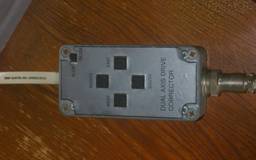
Electronic hand control and computer interface
The electronic hand controller provides a 2 speed fine pushbutton control of the original drive corrector DC motors. It also provides an interface to an external controller such as a desktop PC. Slewing and limited GoTo capability is provided by PC based software via this interface. Hand Controller circuit diagram
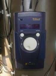
Argo Navis digital setting circles
High resolution shaft encoders are attached the that RA and DEC axes and the Argo Navis “digital telescope computer” by Wildcard Innovations resolves and displays the telescope pointing coordinates in Right Ascension and Declination. Coordinates can also be read out via the serial port.
Sidereal drive and Periodic Error Correction (PEC)
Polar axis (RA) speed is set by the frequency of the AC supply which is very accurately maintained at 50Hz by the electricity utility and corresponds to the solar rate when plugged directly into the mains supply. Of course the actual polar axis speed needed for following the starry sky is not solar which is the speed of the sun across the sky but sidereal which is the speed of the stars across the night sky. The difference is slight but important for long exposure photography. To turn the polar axis at sidereal rate the frequency of the synchronous drive motor supply has to be 50.1369Hz. To correct this problem a separate variable frequency 240V AC generator was designed and built which runs at the sidereal frequency and at the same time corrects the 6 minute cycle periodic error due to non-uniform worm gears. The error correction is accomplished by superimposing a 6 minute period sinusoidal frequency variation onto the base sidereal frequency of 50.1369Hz. The basic design involves a crystal oscillator controlling a phase locked loop (PLL). The programmable feedback counter that sets the output frequency is controlled by the error correction curve stored in an EPROM chip. The phase of the error correction curve is reset every 6 minute cycle by a signal originating from a photo-electronic detector monitoring the rotational phase of the worm gear. The PEC was reduced from about 100 arc seconds to about 30 with this method.
The schematic diagram of the sidereal rate 240V AC supply and periodic error correction circuit is found here.
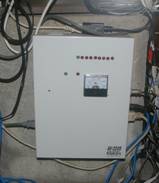
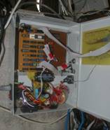
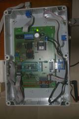
Telescope Controller
The Telescope Controller box integrates the various enhancements added to the original fork mount including the digital setting circles ,the GoTo/Slew hand control box and the autoguide camera and provides an interface for remote control by a PC. It provides front end handling of signals to and from the telescope mount. The Controller ‘talks’ to the computer using a serial port (COM1) to accept commands for reading the telescope coordinates, to slew to specified positions, to initiate autoguiding, etc. The Telescope Controller was implemented using a Parallex “Basic Stamp 2” microcomputer programmed in a version of BASIC language.
Schematic diagram of Telescope controller is found here.
|