
|
Blog |
|
13 December 2018
Ready for another test of the dome drive assembly. After three more visits to Bunnings I got a set of metric tapping tools, appropriate diameter drill bits and some metric grub screws then drilled and tapped M5 screw threads on two sides of the coupling for M5 grub screws. Also drilled indents on the motor shaft for the grub screws to fit. Screwing the two grubscrews into the shaft indents the coupling is now held rigidly to the shaft. Reinstalled the assembly and switched on the power to the motor controller and…. Eureka, it all worked. The dome is moving under electric power. Some quick measurements confirmed that the design criteria is pretty well matched. Initial testing indicated that about 6kg force is required to move the dome and that the coefficient of friction between the rubber tyred driving wheel and the steel dome base ring is about 1, so a force pushing the drive assembly against the dome base must be 6kg or more. The spiral spring providing this “loading” force working over the 24mm horizontal movement range, determined earlier, must provide this force at both ends of the range. A selection was made from a bunch of springs bought from Bunnings after testing by loading them up with weights in the range 6 to 12 kg and measuring the compression range. As it turned out the horizontal movement range of the ring as it rotates (24mm) closely matches the compression range (6-12kg) for the selected spring. The power consumption at maximum speed is 2.1 Amps which translates to 25.2 watts at 12v. This is also well inside the 40 watts rated power of the motor. The maximum speed of the dome rotation measures close to 0.2 meters/sec which translates to 51RPM of the geared motor speed. This compares well with the motor spec. of 40RPM.
Now to get stuck into the rest of the project which includes:
Design and build sensors and electronics to indicate dome position
Write software for Arduino board to read positioning commands from the telescope control computer and drive the dome to the position.
Upgrade telescope control computer software to support the new function of positioning the dome to automatically follow the pointing of the telescope.
Stay tuned. This may take a few months. |
|
11 December 2018
Ready to test version 0.1 of the assembly using a 12v SLA battery and the DC motor and DC motor controller purchased from Motion Dynamics Aust. Pty Ltd. |
|
For initial testing a plywood base was fixed to the inside of the stone wall and the internal stud wall. It appeared rigid enough for basic testing. The test was a miserable failure. The clamping of the special aluminium coupling device between the motor output shaft and the drive wheel shaft wasn’t firm enough at the motor end so the motor shaft just rotated inside the coupling. This is probably due to the motor shaft being 3/8 inch in diameter or about 9.5mm and the coupling bore being 10mm. The 0.5mm difference is too much for the clamping screw to accommodate. |
|
6 December 2018
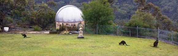
I finally got tired of having to rotate the observatory dome manually every 40 minutes or so while observing especially since most of the observing is done remotely over the local network from my study. It involves going down a flight of stairs and walking about 40 meters to the observatory to reposition the dome opening to where the telescope has moved while tracking the observed target. So I have a new project to mechanise and automate the dome rotation so that the dome opening tracks the azimuth of the telescope.
A bit of high school physics.
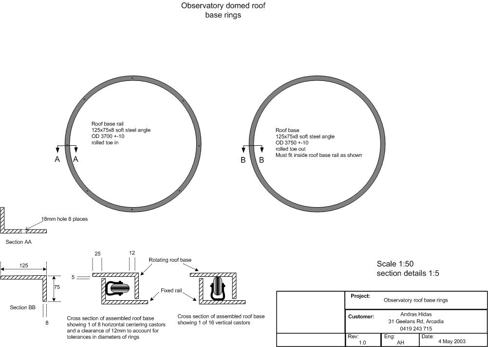
To keep the mechanics simple it was decided to try driving the dome base ring by friction using a suitable size rubber tyred wheel and a geared DC motor of suitable power and speed. DC motor is needed because the rotation can be in either direction. This design should work since the dome is easy to turn with the dome base steel ring resting on 8 ball bearings. (see dome base design here). To measure the tangential force required to move the dome a weight on a rope over a pulley was rigged up and the weight increased until the dome started rotating. This turned out to be between 5 and 6 Kg or about 50 Newtons. This will be the force of friction required to between the driving wheel and surface of the base ring. Of course this is the maximum required at the start of motion to overcome the initial friction of the bearings. Once moving the force is less to keep the dome moving. The other variable is the “normal” force (the force pushing the driving wheel against to ring surface) on the wheel to produce the driving friction. The simple formula for the force of friction between two surfaces is Fr=μN where Fr is the force of friction in the direction of movement, μ is the coefficient of friction between the two surfaces and N is the force pushing the two surfaces together. In this case it’s the force to be applied pushing the wheel against the ring. Assuming, conservatively that μ is about 0.5 (between rubber tyre and panted steel surface) the force on the wheel to produce 5kg of friction is 10kg. Calculating the speed and power of the geared DC motor required assuming a 75mm diameter driving wheel (sometimes called a capstan) and maximum speed for the dome of one revolution per minute or 6 degrees a second. In terms of linear motion, the speed desired is πD (D is inside diameter of ring = 3.50m) or 3.14 x 3.5= 11.0 metres/minute or approx 0.2 metres/second. Also assume a constant force of 50 Newtons (as estimated above) being needed to keep the dome moving. Power (watts) is work/second ie joules/second and work is force x distance. So work required in one second is 50 Newtons x 0.2 metres = 10 Watts. That is a motor producing at least 10 watts of power is required. To specify the motor properly the 50 Newton force needs to be converted to torque and the linear speed of 0.2m/s converted to revs/minute. Torque = rF (radius of rotation x tangential force at radius r) i.e. for 75mm diameter wheel (0.0375m radius) and 50 Newton tangential force the torque is 0.0375 x 50 = 1.875 Newton metres (Nm). Rotational speed is the linear speed divided by the circumference of the driving wheel revolutions per second or 0.2/(0.075x3.14) = 0.849 revs/sec or 51 revs/min. Because of all the variables, non uniformities and inefficiencies involved this result can only be considered as an “order of magnitude” estimate.
Components needed
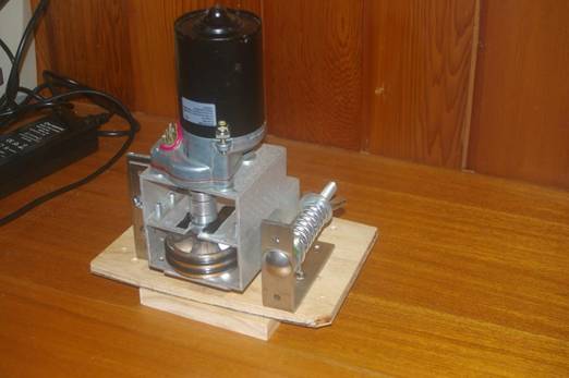
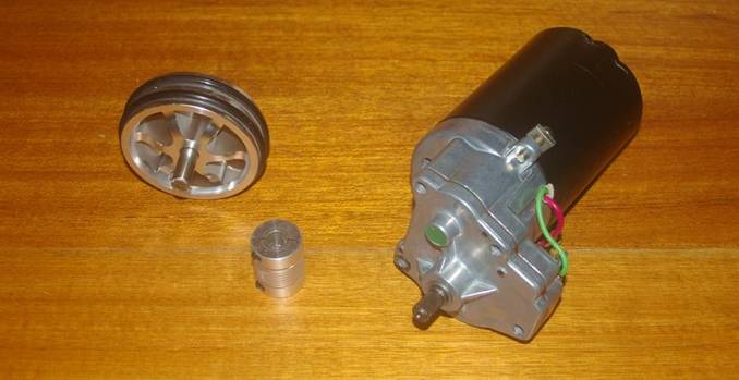
So.. we need a 10 Watt DC motor providing 1.875 Nm torque geared down to 50 revs/min. To be on the safe side say 20watts and 5Nm at 50revs/min The other critical component required is a proper coupling device that connects the motor shaft to the driving wheel. Apart from matching the two shafts it has to be able to transmit the required torque. Following these calculations, to be doubly sure, a DC motor running on 12V 40Watt power, 29Nm torque with max speed of 40revs/min was sourced along with a suitable coupling and a 75mm driving wheel. See photo below. |
|
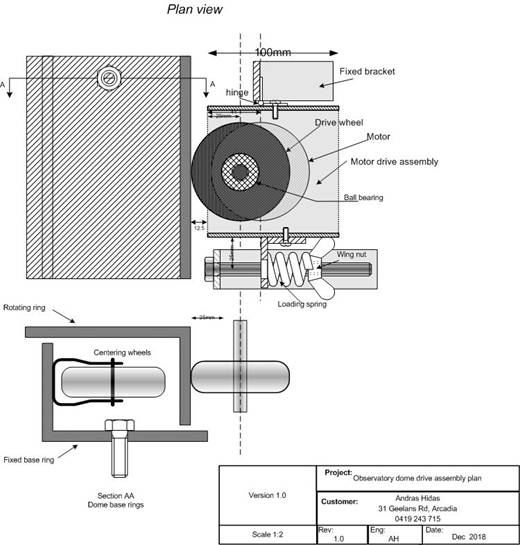
Mechanical design and some metalwork
There are other issues to be considered. While the moving base ring floats on 8 vertically mounted fixed ball bearings the ring is kept centred by 3 fixed horizontally mounted casters with 12mm spacing to the ring to ensure that the ring can’t get jammed. This implies a 24mm horizontal movement range that the friction drive assembly need cope with while maintaining sufficient friction to drive the base ring. The answer is to spring load the assembly using a spring that applies sufficient pressure over the full range of the horizontal movement. In addition the base supporting the drive assembly must be rigidly stable relative to the fixed base ring to maintain the frictional force between the drive wheel and the moving ring. It was decided to weld a piece of 6mm steel plate to the base of the fixed ring. |
|
|