
|
Blog |
|
27 January 2019
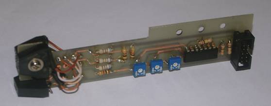
Update on the dome drive project. I have worked hard since the last blog entry to design and implement the printed circuit assembly that senses and reports the position of the dome opening that’s required as feedback for the software that will control the dome’s movements. The circuit is based on three reflective object sensors that sense and count reflective strips spaced at 1 degree intervals around the inside surface of the dome base ring. It works on the same principle as shaft encoders normally found on the back of electric motors whose rotation needs to be monitored precisely. Two sensors are required for keeping count of the distance moved and the direction of motion. The third sensor detects an index strip that marks zero or north point and resetting the degree counters. See circuit diagram for the sensor assembly.
|
|
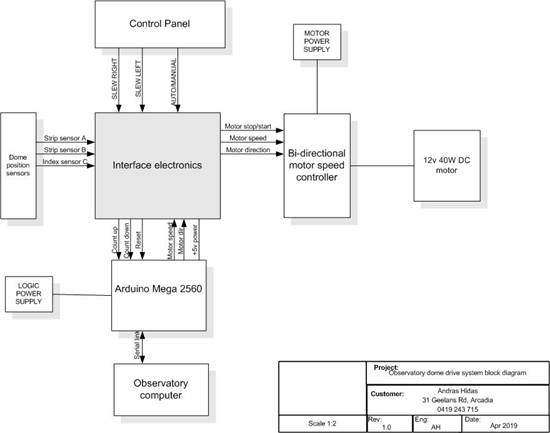
The design for the control electronics incorporating the Arduino microcontroller board and interface to the dome sensor assembly and the observatory computer is finished. Control electronics circuit diagram is here. A feature of the dome control system is it’s dual mode operation. The dome would normally be controlled from the telescope control software running on the observatory computer. It will be able to be slewed to any position by the operator or set to track the sidereal motion of the telescope as it tracks a point in the sky. In addition the dome control will be able to be switched to fully manual operation in isolation from the computer. Also, fired up the Arduino IDE software development environment on another computer. The steep learning curve for writing C++ code for the Arduino was negotiated without too much difficulty as C++ code is very similar to the old Turbo C used to code the observatory software. The critical elements of the Dome Control software have already been tested successfully. These were the control loop tasks including monitoring the regular positioning commands, serial input from the observatory computer, sending the current dome position back in response and updating the dome motor drive control voltage and direction. The current dome position counter in the Arduino is updated by interrupts from the count up and down pulses from the dome sensor and resolver circuits.
|
|
4 February 2019
The dome control software running on the Arduino module is now finished and tested offline using a test computer running the observatory computer software and some test circuits that simulate the dome sensor pulses. Arduino code is shown here.
Last week the observatory computer went down following a two week period of being switched off and not used during the mid-January heat wave. Temperatures in the observatory regularly reached very close to 40 degrees C and even over 40 some days. It appeared at first to be a major disaster as the OS (Widows XP) would not boot, so a faulty hard disk drive was suspected. An identical computer that was replaced two years ago due to lightning damage was still available and it would also not boot from the observatory disk. Because the older computer was suspect for other reasons, as a last resort it was decided to try the power supply from the old machine in the current faulty computer and it worked. So the observatory is now back online and waiting for cloudless skies.
Not much observing was done during January due to cloudy skies and a series of heat waves. Only two new NEOs were able to be observed and confirmed during January. See MPECs |
|
3 April 2019
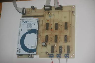
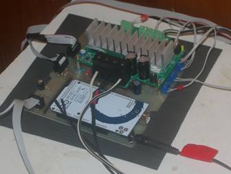
Update on the ‘project’. Very busy the last couple of months designing the printed circuit layout and making the double sided printed circuit board for the dome drive control electronics. This cicuit board integrates the observatory computer interface, the dome position sensor, the dome control processor (Arduino Mega 2560) and the motor control circuit. (see picture). The dome position sensing system was completed and tested after applying 360 (marking 1 degree intervals) reflecting strips to the inner surface of the dome base ring. Final testing of the full system with software and all elements interconnected was started last week. Surprisingly only a small number of software bugs were found with the electronics and motor drive system working well. There will be a wear and tear issue with the friction drive wheel rubber tyre rings not quiet being up to the task in the long term. A more robust rubber tyre will be needed in the future. There is still an unresolved software issue with the integration of the dome control function in the observatory control computer. Otherwise the system is ready to be properly packaged up and cabling for power and communications tucked away permanently. It was a buzz seeing the dome slit follow the telescope tracking the sky automatically.
|
|
Dome control circuit board with Arduino module plugged in |
|
Assembled dome control electronics under test |
|
Dome drive system block diagram: |
|
Normal observatory activity continued during February and March with two successful NEO follow up observations due to very few clear nights available during the month. The March total was 9 NEOs. The up to date results fir this year can be seen here. |
|
15 May 2019
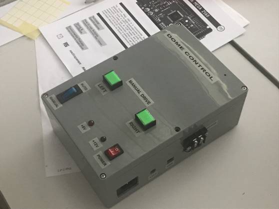
Since my last post the project has progressed with few hick ups and is virtually finished. After confirming the correct operation of the integrated hardware I packaged all the components shown on the block diagram (including the interfacing electronics board, Arduino module, the bi-directional motor speed controller and the 12VDC power supply) into a suitable sized plastic box purchased from Jaycar . There is access form the outside for a separate 12VDC source and USB port for software updates. The 12VDC for the Arduino module generates the 5VDC for the logic. |
|
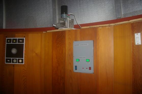
The cabling inside the observatory is still a mess but having all the bits in a box made serious testing a lot easier. In normal (Auto) operation the orientation of the dome opening is controlled by the observatory Telescope Control software continuously sending to the Arduino module in the box the azimuth angle where the telescope is pointing. The Arduino commands the motor to rotate the dome to the corresponding compass direction. It also sends the current dome position back to the computer for display on the Telescope Control screen. The dome control box has a Manual mode as well, where the dome can be rotated manually in either direction by pressing one of the manual drive direction buttons.
During testing it was found that aligning the dome opening with azimuth of the telescope pointing does not always result with the telescope and guide scope assembly pointing at the centre of the dome opening. One reason for this error is that the telescope mount is slightly offset from the centre of the dome ring. The other reason is that the telescope with the piggy backed guide scope requires a larger dome opening when facing due east and due west then it does when facing north and south. That is, the guide scope would not be looking through the opening when pointed east or west. The solution is that, instead of using the raw azimuth angle from the telescope controller directly, the azimuth angle is used as a pointer in a large lookup table which stores the correct dome positions at 10 degree intervals at four different altitudes. Intermediate positions are calculated by interpolation between 10 degree points. Creating the lookup table was a very laborious exercise taking many hours. Points near the zenith were especially difficult the set up.
Just as everything started to fall into place, having already done some real fully automated survey runs, with the dome following the telescope pointing, the motor driver board in the box died. Apparently the contents of the NVRAM containing some motor setup parameters, has evaporated. I’m currently awaiting service or replacement from Motor Dynamics.
Routine NEO follow up work resulted in the confirmation of 11 new NEOs and one new comet with corresponding MPECs. I’m up to 5 for the month of May.
|
|
30 June 2019
The dome drive project is finally finished. The last few weeks were spent tracking down some nasty problems mostly associated with the operation of the dome base ring position encoder. The decoder circuitry generating the pulses counting the one degree intervals in the reverse direction intermittently dropped or added pulses. This resulted in incorrect dome position indication. Other problems involved communication between the telescope control computer and the Arduino computer controlling the dome. The problems were fixed by software workarounds.
|
|
Score of MPECs for the last two months of routine NEO confirmations is: May 10; June 15; ( link here) )
26 May 2019
Made a concerted attempt at recording the light curve of binary NEO/PHA (Potentially Hazardous Asteroid) 66391 (1999 KW4) during it’s close approach on 25 May 2019. This is a very interesting double asteroid with it’s components in a tight orbit around each other. Unfortunately the range of brightness change during it’s period of rotation of 2.7 hours is only about 0.2 magnitudes which was almost swamped by random variability caused by bad seeing. The 310 observations of magnitude taken over 2.5 hours was not worth submitting to MPC (Minor Planet Center) |
|
|